Conveyors, a hopper and a rock-box chute fitted into a minerals plant that kept running
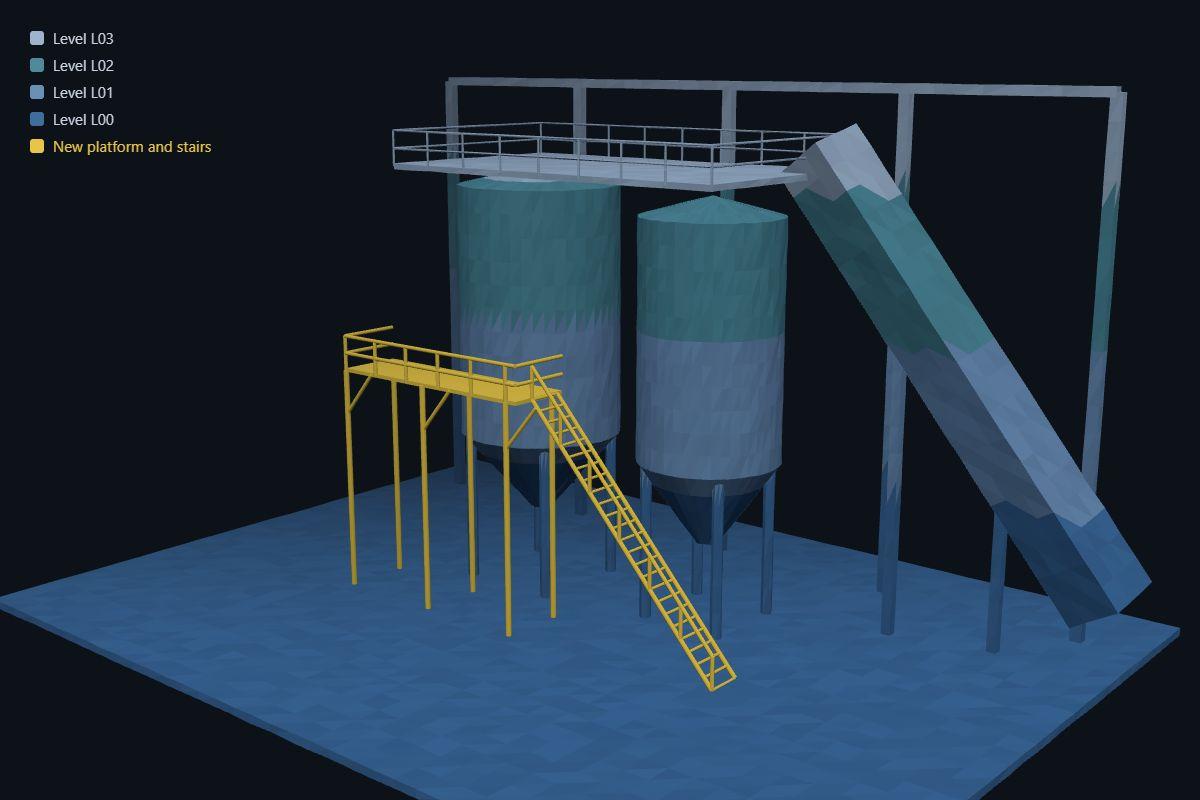
A minerals plant needed new conveying equipment in areas already full of steelwork, chutes and running conveyors. We designed five pieces against laser scans of the plant: a conveyor under an existing chute, a conveyor extension, a hopper, a support frame for a bought-in feeder and a rock-box chute. Each one went to the workshop as a complete drawing package.
- Industry
- Minerals processing
- Region
- Europe
- Service
- Plant engineering
- pieces fitted into the running plant
- 5
- pieces fitted into the running plant
- drawings for the workshop
- ~30
- drawings for the workshop
- plant grid and levels measured from the laser scan
- ±20 mm
- plant grid and levels measured from the laser scan
- conveyor frame under an existing chute
- 13 m
- conveyor frame under an existing chute
What had to be solved
- The plant kept running, so every piece had to fit the first time.
- The new equipment had to fit between existing steelwork, chutes and conveyors, with little room to spare.
- Each piece had to connect to what was already there: chute outlets, conveyor heights and support steel.
What the client has now
- Five new pieces of equipment fitted into a plant that kept running.
- Every connection was checked against the scan before anything was built.
- Each piece went to the workshop as a drawing package with its parts list.
How we approached it
- 01
Designed against the scan
The client laser-scanned the areas. We measured the plant grid and levels from the scan to ±20 mm and designed every piece against it.
- 02
Two conveyors
A new conveyor with a 13 m frame placed under an existing chute, and an extension on HEB 200 beams that connects to an existing conveyor.
- 03
Hopper and feeder frame
A hopper with AR wear liners and rubber flaps, and a support frame for a bought-in feeder.
- 04
Rock-box chute
A 1.6 t rock-box chute in S355 steel, where the material lands on material instead of on the steel.
The work, step by step
Illustrations. Click an image to enlarge it.
What was handed over
- 3D models of five pieces, placed in the scanned plant
- About 30 drawings: assemblies, weldments and parts
- Parts lists and BOMs for the main assemblies
- Plant grid and levels measured from the scan
- Autodesk Inventor
- Autodesk ReCap point clouds
This project is part of our plant engineering work.
Send us one area of your plant.
Tell us what has to change and what scan data you have. In 20 minutes you will know what the model and the design would take.